
Zoeken
Search
971 results were found.
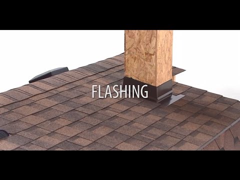
Flashings: eaves, rakes, walls, chimneys, etc.
All areas on the roof surface where roof planes intersect or protrude through the roof surface (chimneys, vent stacks, dormers, walls, etc.) require flashings. Flashing is the construction procedure which is necessary to make these areas waterproof. Metal flashings are effective, because when properly installed, they can help accommodate roof, chimney, wall, or structural movements due to settlement, expansion, and contraction. Roof flashing drains water and is constructed in a system to work with the effect of gravity. When designed and installed correctly, flashings can only be defeated by water running upward. This can happen in the presence of snow, ice or wind-driven rain.

Flashings installation
Drip edge flashing on eaves and rakes
Drip edge is the simplest flashing. It is used at the rakes and eaves. It provides efficient water shedding and protects the underlying wood from rotting. The drip edge should be made of a corrosion-resistant material that extends back at least 8 cm from the roof edge and bends downward over the fascia/roof boarding. Apply the drip edge underneath the underlayment along the eaves to allow water to shed smoothly off the roof if it gets under the shingles.
The rake flashing is installed on top of the underlayment to prevent wind-driven rain from getting beneath it.

Drip edge flashing, used on rakes and eaves

Rake flashing, installed on top of the underlayment to prevent wind-driven rain from getting beneath it.

Drip edge flashing, used on rakes and eaves
Rake flashing, installed on top of the underlayment to prevent wind-driven rain from getting beneath it.
Flashing against a vertical sidewall
Roof planes which are finished against a vertical wall at the end of shingle courses are best protected by metal flashings placed over the end of each course. This method is called “step flashing”.
These requirements for applying step flashing shingles against vertical sidewalls must be followed:
- The width of the step flashing on the deck must be at least 10 cm wide.
- The height of the step flashing installed against the vertical surface must be at least 10 cm high.
- For step flashing application, the pieces of flashing must overlap each other by at least 5 cm.
- The length of the step flashing pieces is approximately 25 cm and depends on the type of shingles being applied.
- The material used for step flashing must be corrosion resistant.

Extend the underlayment approximately 10-12 cm up against the vertical wall. Place the first flashing piece over the end of the starter strip, and finally position it so that the end shingle in the first course covers it completely. Secure the horizontal flange to the roof with two nails. Roofing nails should be placed in the uppermost 5 cm area of the step flashing piece, to avoid leakage. Next, apply the first course of shingles up to the wall. Position the second step flashing piece over the end shingle in the first row cover head-lap of the shingle. This will permit the shingle in the second course to cover it completely. Always use some bituminous mastic to bond down the shingles and step flashing. The second course of shingles follows and the end is flashed as in previous courses. Continue up the roof or sidewall area in a similar manner.
Side wall flashing can also be installed as a single continuous piece. This is common against stucco walls and with tile roofing. Be sure to turn up a hem (water stopper) on the horizontal roof side of the flashing. Metal flashings are fixed with the small clips to the roof. When you apply the shingles, do not nail the shingles through this metal profile but glue the end of every shingle on the profile edge.

Counter flashing
Counter flashing or cap flashing must be installed, lapping the step flashing or continuous metal flashing, so that water cannot run into the joint. This is done by raking out the mortar joint to a depth of 2-4 cm, inserting the bent edge of the flashing and refilling with mastic. The length of the counter flashing depends on the roof pitch and the brick size. Always start at the lowest point, overlapping each by at least 7 cm. Cap flashings can also be made as a one continuous piece.
